
How an engine borescope traced rising oil consumption to failed inlet valve stem seals on cylinders 1 and 6, before the engine was opened
Oil consumption that climbs slowly is one of the hardest faults to diagnose on a diesel generator set. Nothing has failed outright, no alarm has tripped and the unit still carries load, but the lube oil level keeps dropping, and every extra litre forces a decision: keep running and monitor, or take the machine offline. A borescope inspection is the cheaper half of that second option, because it tells you what is wrong before anything is opened.
On this Caterpillar 3406 generator, that decision was settled in a single borescope inspection. With the valve cover and injectors removed and the crankshaft positioned at bottom dead centre, the inspection team steered a probe through the injector bore and photographed the combustion side of the engine in every cylinder. The result was a confirmed root cause, excessive carbon build-up on cylinders 1 and 6 caused by failed valve stem seals on the inlet valves, and a repair that could be planned, quoted and resourced before a single head bolt was turned.
Why rising oil consumption usually starts at the top end
Every oil-consumption diagnosis starts with the same question: is the oil entering at the top end, or from below? A borescope inspection answers that question before a single gasket is broken. On an inline-six diesel such as the 3406, lube oil reaches the combustion chamber by four routes: past the inlet valve stem seals and guides, past the turbocharger seals, past worn piston rings and liners, or through the crankcase breather system. Only the breather can be checked from outside; the other three sit inside the engine and each one assumes the engine comes apart.
The top end is the cheapest internal route to rule in or out, because the inlet tract and the valve heads sit almost directly behind the injector bore. A stem seal that has hardened, cracked or lost its grip no longer wipes the stem clean, and oil is drawn into the port on every intake stroke. Some of it burns; what does not burn cokes onto the hot valve head, the seat and the surrounding deck, and the deposit keeps growing for every hour the engine runs.
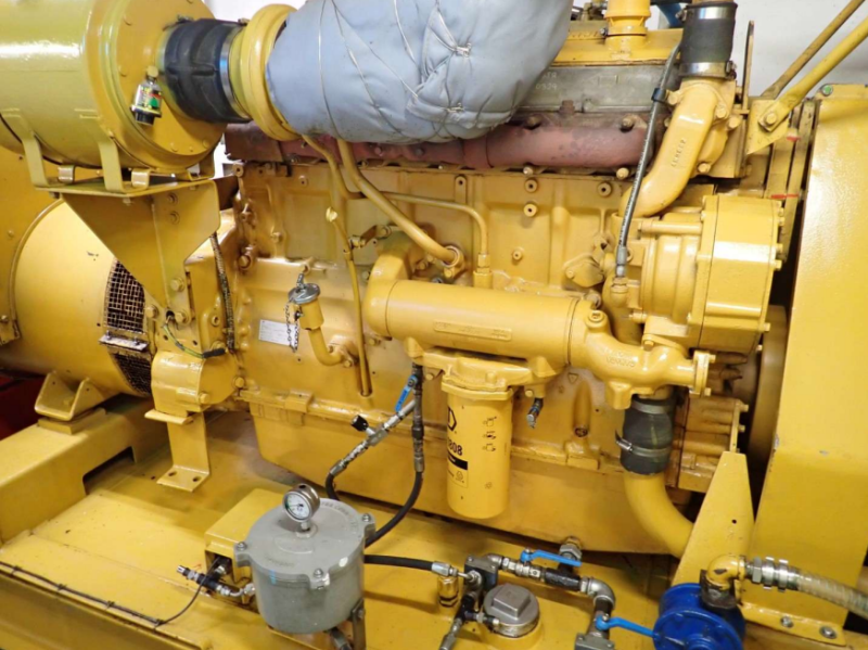
Figure 1. The Caterpillar 3406 generator set: a unit that reported rising oil consumption while still carrying load.
Setting up the inspection
The preparation for this borescope inspection was deliberately minimal: remove the engine valve cover and the injectors, then position the crankshaft at bottom dead centre for the cylinder under examination.
Bottom dead centre does two jobs. It drops the piston crown far enough down the bore to expose the full liner surface, and it opens a clear optical line from the injector bore up to the valve heads, so the probe can be aimed at the seat rather than at the piston. On a multi-cylinder engine it also makes the record readable: each frame is tagged with the cylinder number, the probe direction and a timestamp, so anyone reviewing the file later can reconstruct exactly where the image came from.
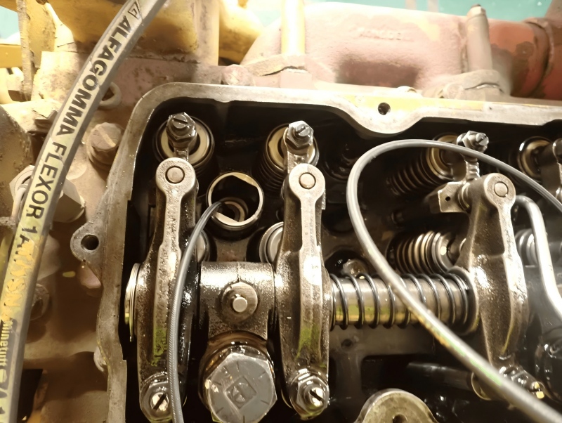
Figure 2. Valve cover off and injectors removed: the only dismantling this borescope inspection required.
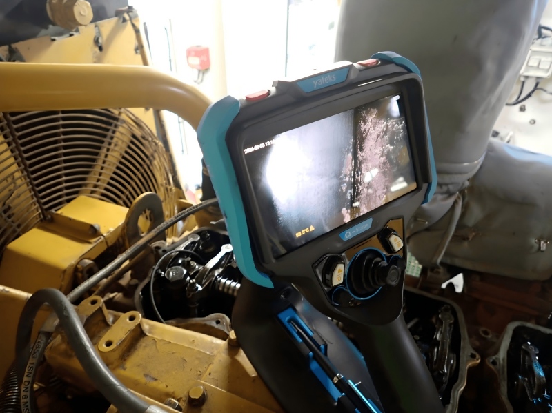
Figure 3. The probe at work, with the live image read on the Q-Scope display beside the engine.
Inserting the probe is the easy part; the discipline around it is what produces usable evidence. Clean the injector bore before the probe goes in, support the insertion tube so it does not scrape the bore wall, move the tip slowly, and capture both video and stills at each station: video for context, stills for the report.
What the borescope inspection found
The borescope inspection produced a per-cylinder record, and the record read in one direction from the first frame. Carbon was the first thing to appear, and it appeared in quantity. Around the spacer plate the deposit had formed a crust rather than a film, with the cauliflower surface of oil that has been baked on over a long service interval.
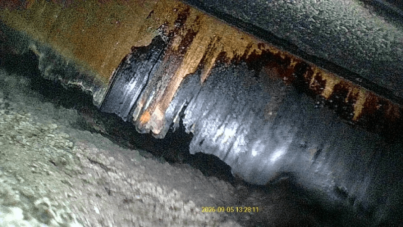
Figure 4. Carbon next to the spacer plate: a crust, not a film, after a long service interval.
Higher up, at the valve heads, the picture changed character. The valve face was not dry carbon; it carried a wet, glossy film of oil that was arriving faster than the engine could consume it.
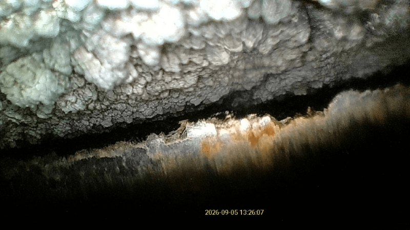
Figure 5. Wet oil on the valve head: the detail that separates a seal failure from a combustion problem.
The comparison that made the diagnosis defensible was between cylinders. Viewed from cylinder 2, the stem seal area was relatively clean: the seal and the guide were still legible as separate parts, with light deposit only. Viewed from cylinder 1, the same area was buried under oil and carbon, and the seal was no longer distinguishable as a component. One engine, one service interval, one fuel, and two cylinders behaving differently from the rest.
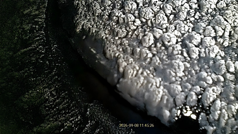
Figure 6. Reference frame: the stem seal area as seen from cylinder 2, still legible and lightly deposited.
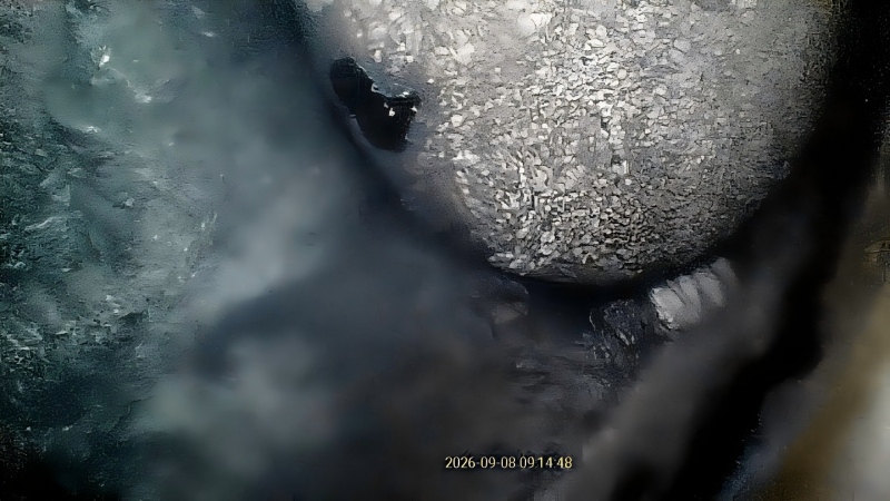
Figure 7. Cylinder 1, same area, same engine: oil and carbon together, with the seal no longer readable.
The inspection report reduced all of it to one line: excessive carbon build-up found on cylinders 1 and 6, caused by the failure of the valve stem seals on the inlet valves.
The frames also carry their own timestamps, and those timestamps are part of the value. They span 5 to 16 September 2026, which means the deposit was photographed more than once during the diagnosis rather than reconstructed from memory afterwards. A borescope inspection that repeats the same station on a second visit produces a series, not a snapshot, and a series is what supports a repair decision on an engine that is still earning.
How the images add up to a seal diagnosis
Ring and liner wear leaves a different signature on a borescope inspection image. You would expect a glazed or scuffed liner running the length of the bore, an oil film spread evenly across all cylinders, and a rise in blow-by that the operator notices before the oil level on the dipstick.
Here the deposit was concentrated at the top of the bore, on the inlet side, and on two cylinders rather than six. That is a localised top-end failure, not a global one.
Wet oil on the valve head is the detail that closes the argument. Dry carbon can come from combustion quality, from fuel, or from oil mist in the inlet air. Oil that is still liquid on the valve face means oil is reaching that surface faster than it can be burned, and the only path oil has to that surface is past the stem seal.
The distribution of the carbon adds a second clue. Deposit sitting below the valve, next to the spacer plate, is carbon that formed above the valve and was then carried down into the bore on the intake charge: the footprint of oil entering from the top of the cylinder rather than migrating up past the rings.
The repair decision: cylinder head replacement
The action taken on this engine was to replace the cylinder head. That is a heavier decision than resealing the valves in place, and the images explain why. Once a seal has leaked long enough to build the crust visible beside the spacer plate, the deposit has also had time to settle on the seats and faces, and lapping new valves into a carbon-contaminated head leaves a leak path that comes back as a compression fault a few hundred hours later.
Replacing the head also turns an open-ended diagnosis into a scheduled job. The parts list is known, the labour is known, and the unit goes back into service against a date instead of an estimate. That is the practical value of the borescope inspection: not that it found carbon, which the operator already suspected, but that it named the cylinders, the component and the repair, in evidence that fits in a report.
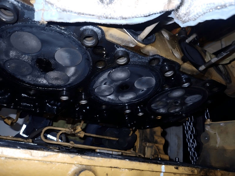
Figure 8. The removed head: the confirmation that the borescope images had read correctly.
What a borescope inspection is worth to a maintenance team
The return on a borescope inspection on an engine of this size is measured in decisions that do not have to be guessed.
- No disassembly. Only the valve cover and the injectors come off, so the engine is not disturbed in order to gather evidence.
- A parts list before the work order. Knowing that cylinders 1 and 6 are affected, and that the seals are the failure point, lets the workshop order one head and one gasket set, once.
- Healthy cylinders stay closed. The remaining cylinders are documented as inspected and acceptable, so no joint is broken for the sake of curiosity.
- A timestamped record. The images are evidence for an OEM, a warranty claim, an insurer, or the next technician who inherits the machine.
- A baseline for trending. Repeat images at the next service show whether a deposit is stable, or growing.
A checklist for your next engine borescope inspection
A repeatable borescope inspection routine looks like this.
- Confirm the trend, not just the symptom: litres per hour, logged across a service interval.
- Remove only what the inspection needs, the valve cover and the injectors, and leave everything else closed.
- Set the crankshaft to bottom dead centre and verify the position on the timing marks, not by feel.
- Work cylinder by cylinder, and put the cylinder number on every frame.
- Photograph three stations per cylinder: liner and ring band, valve heads and seats, deck and spacer plate.
- Move the probe slowly and capture video as well as stills; motion blur is the most common reason an image cannot be used in a report.
- Include a known-good cylinder from the same engine as a reference frame.
- Write the finding as a sentence, component, cylinder and mechanism, not as a folder of photographs.
Choosing a borescope that survives engine work
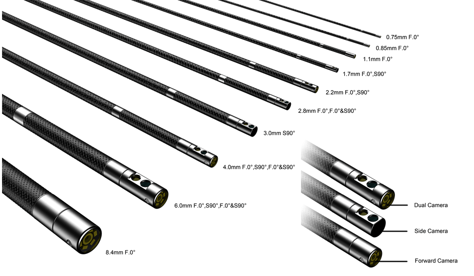
The instrument in these photographs is a Yateks Q-Scope. Brand aside, four properties decide whether a borescope inspection produces evidence or just pictures.
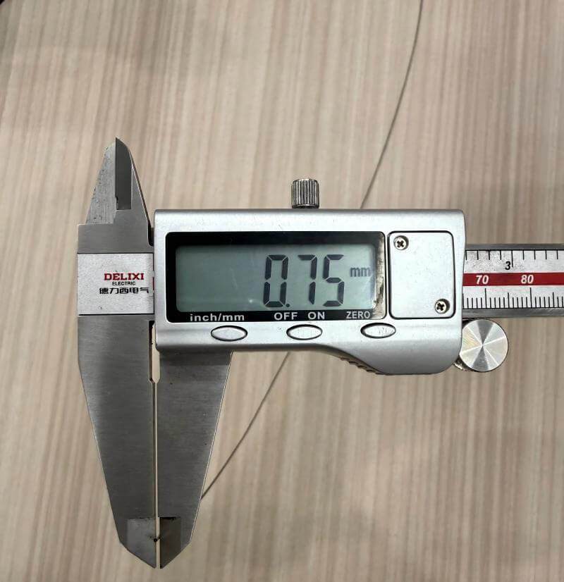
- Probe diameter. The injector bore sets the ceiling: 4 to 6 mm covers most diesel work, while 2.8 mm opens tighter passages and small ports.
- Two-way steering will reach a valve head; four-way steering lets you look back at the seat and along the bore wall in the same pass.
- Light control. Dimmable illumination matters more than maximum brightness, because a hot spot on a wet valve head erases exactly the detail you are trying to read.
- Capture and export. Timestamped stills and video that open without a proprietary viewer are the difference between a file that survives an audit and one that does not.
FAQ
Can a borescope inspection confirm valve stem seal failure?
A borescope inspection confirms the evidence pattern, oil on the valve head, carbon concentrated on the inlet side and a visible difference between cylinders, without disassembly. It cannot measure seal clearance to a tolerance; that needs the head off. For a maintenance decision the pattern is enough, because it identifies both the cylinder and the component.
Is a borescope inspection ever enough on its own?
Sometimes. Clean liners and dry valve heads usually redirect the diagnosis towards the turbocharger or the breather instead of a teardown. In this case the images did the opposite: they justified opening the engine, and they made sure the right parts were on the bench when it was opened.
Which cylinders should be inspected?
All of them, with at least one clean reference. Two cylinders had failed here, and the credibility of the report came from the four that had not: six frames read side by side show a pattern that no single image can.
Conclusion
This Caterpillar 3406 is a small, ordinary example of what a borescope inspection does well: it turns a symptom into a component. The engine kept running, nothing was dismantled to find the fault, and the repair that followed, a cylinder head replacement, was chosen on evidence rather than by elimination.
If your team is chasing oil consumption, exhaust smoke or an unexplained loss of compression, the fastest route to an answer often starts through a five-millimetre hole. Yateks builds industrial borescopes for that work, and publishes cases like this one so the next inspection starts from a reference frame rather than from scratch.